GPU Pathtracer
Realtime Pathtracer with MIS and BVH in GLSL/OpenGL
Overview
This is a GPU path tracer written in GLSL. The whole integrator runs in a fragment shader: every frame traces one path per pixel and the result is averaged into an accumulation texture, so the image converges live in the viewport. It supports next event estimation with MIS, diffuse, specular, microfacet, and conductor materials, textured triangle meshes with a BVH, thin-lens depth of field, HDR environment maps, and Intel OpenImageDenoise.
Cover Render
128spp, 1303x2000, no denoising, 2m 19s. ACES tone-mapping
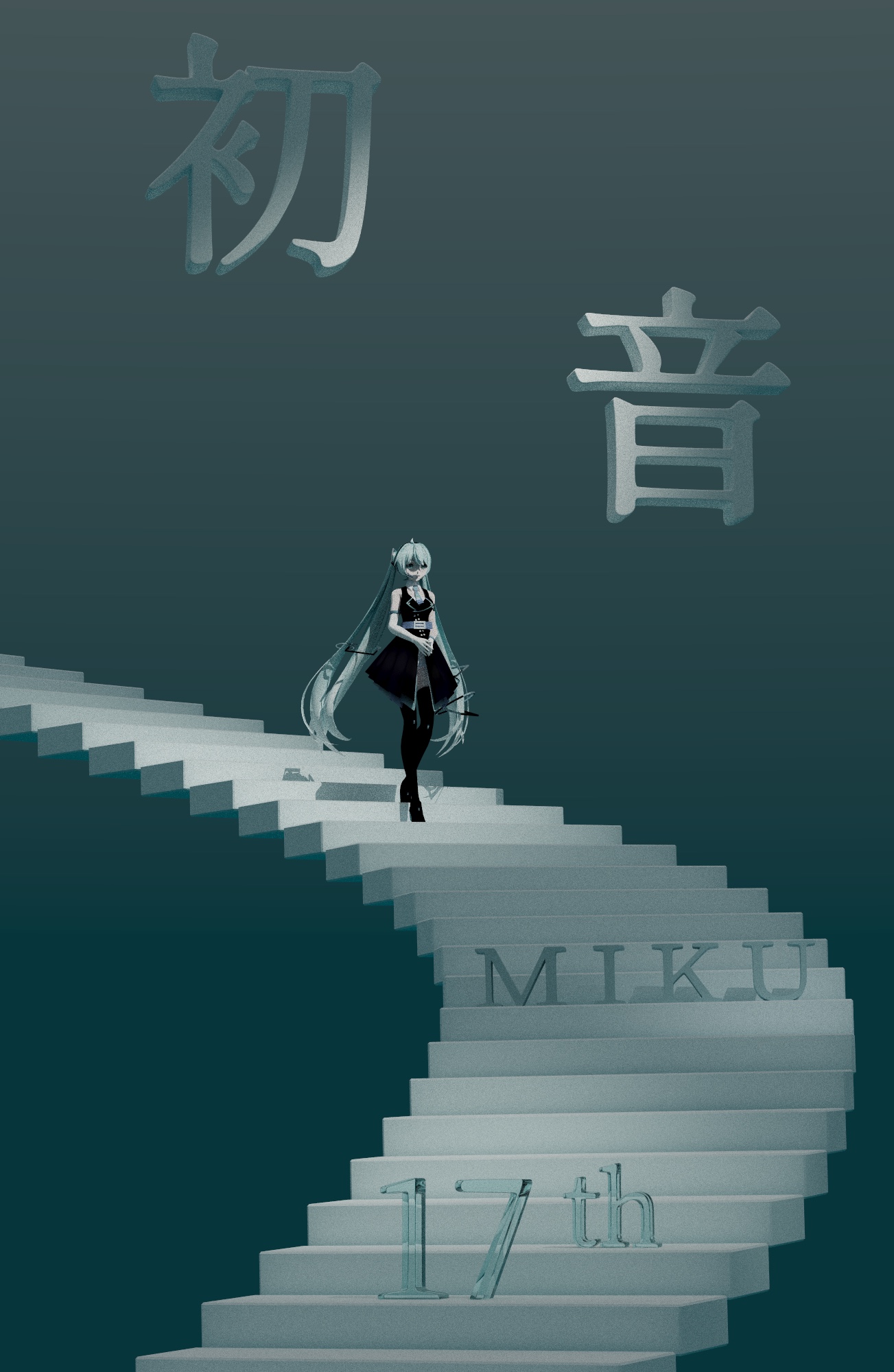
Character model by YYB-Era, scene models, composition, lighting by me
Integrator
The integrator is a loop over bounces, up to 10 deep, carrying two values: throughput, the product of every BSDF, cosine, and 1/pdf along the path so far, and accumLight, the radiance sent back to the camera. At each intersection:
- If the surface is emissive, add its
Letimes throughput, but only if this is the camera ray or the previous bounce was specular. Then stop. - If the surface is diffuse or microfacet, compute direct lighting at this point with MIS and add it times throughput. Specular surfaces skip this step.
- Sample the BSDF for a new direction with a fresh 2D random variable, multiply throughput by
bsdf * |cos| / pdf, and spawn the next ray from the hit point. - If the ray escapes the scene, add the environment color times throughput and stop.
Step 1 is what keeps the estimate unbiased. Direct light on a diffuse surface has already been counted by NEE in step 2, so hitting the light again with the bounce ray must not add Le a second time. The exception is specular surfaces: their BSDF is a delta, so the light strategy can never pick the mirror direction, and the only way to see a light in a mirror is through the bounce ray. A prevSpecular flag carries that decision to the next iteration.
Direct Lighting with MIS
The direct lighting function combines two estimators with the power heuristic:
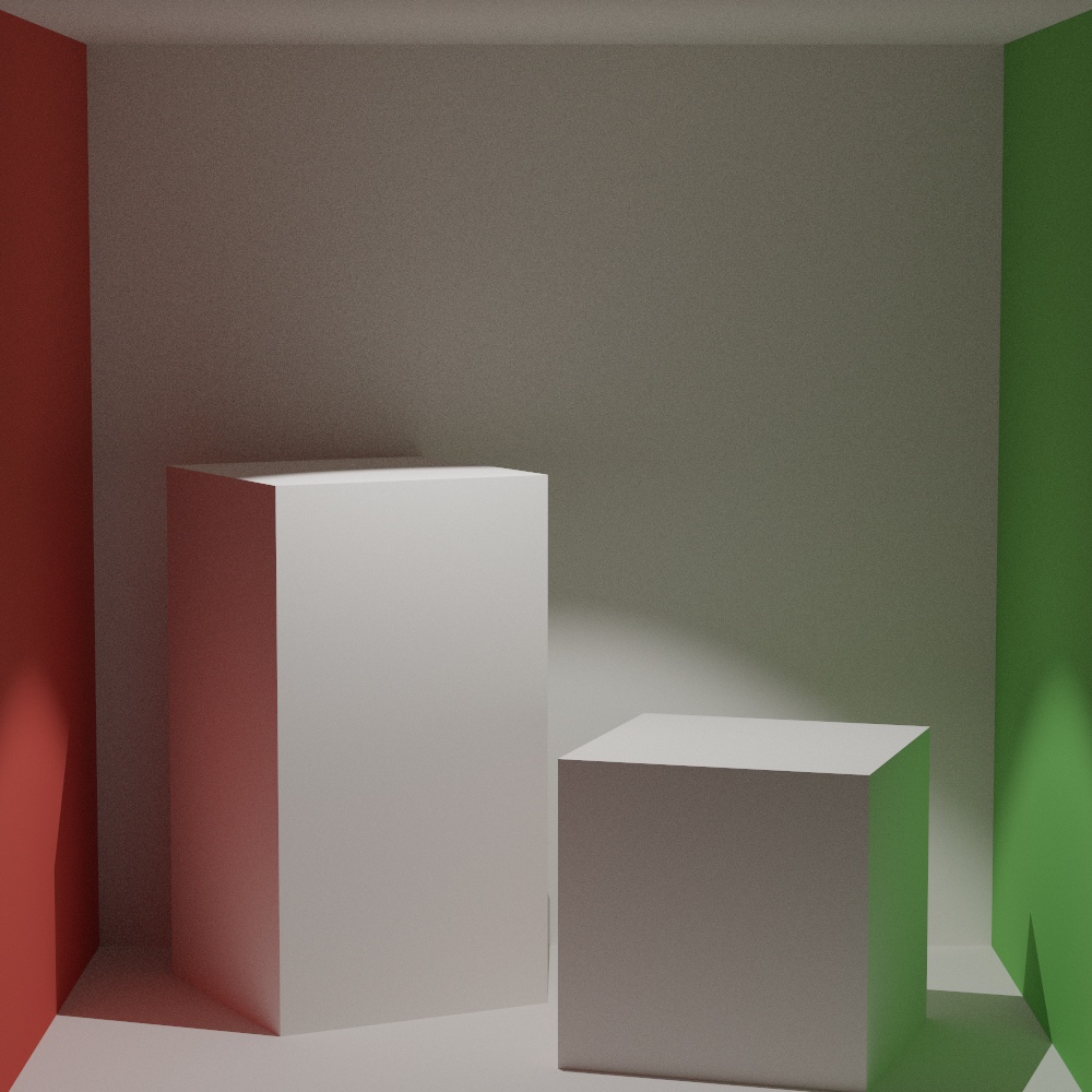
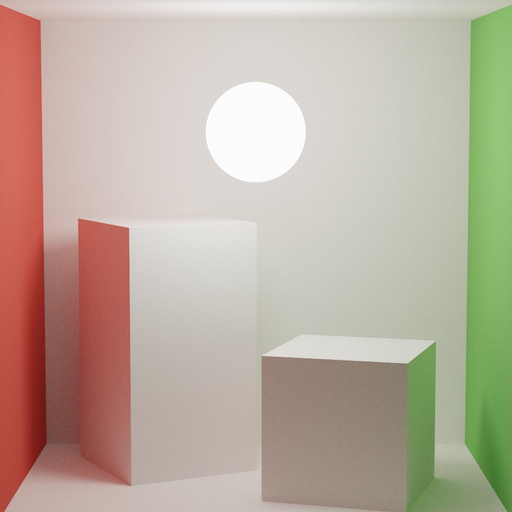
- Light strategy. Pick one light uniformly (the environment map counts as one more light), sample a point or direction on it, shoot a shadow ray, and evaluate the BSDF toward it. The contribution is weighted by
pdf_light² / (pdf_light² + pdf_bsdf²), wherepdf_bsdfis the BSDF’s pdf for that same direction. - BSDF strategy. Sample the BSDF, trace the ray, and only count it if it lands on the light that was chosen in the first step. Its weight uses the light’s pdf for that direction, which is what
Pdf_Licomputes: the rectangle’s area pdf converted to solid angle, or the sphere’s cone pdf.
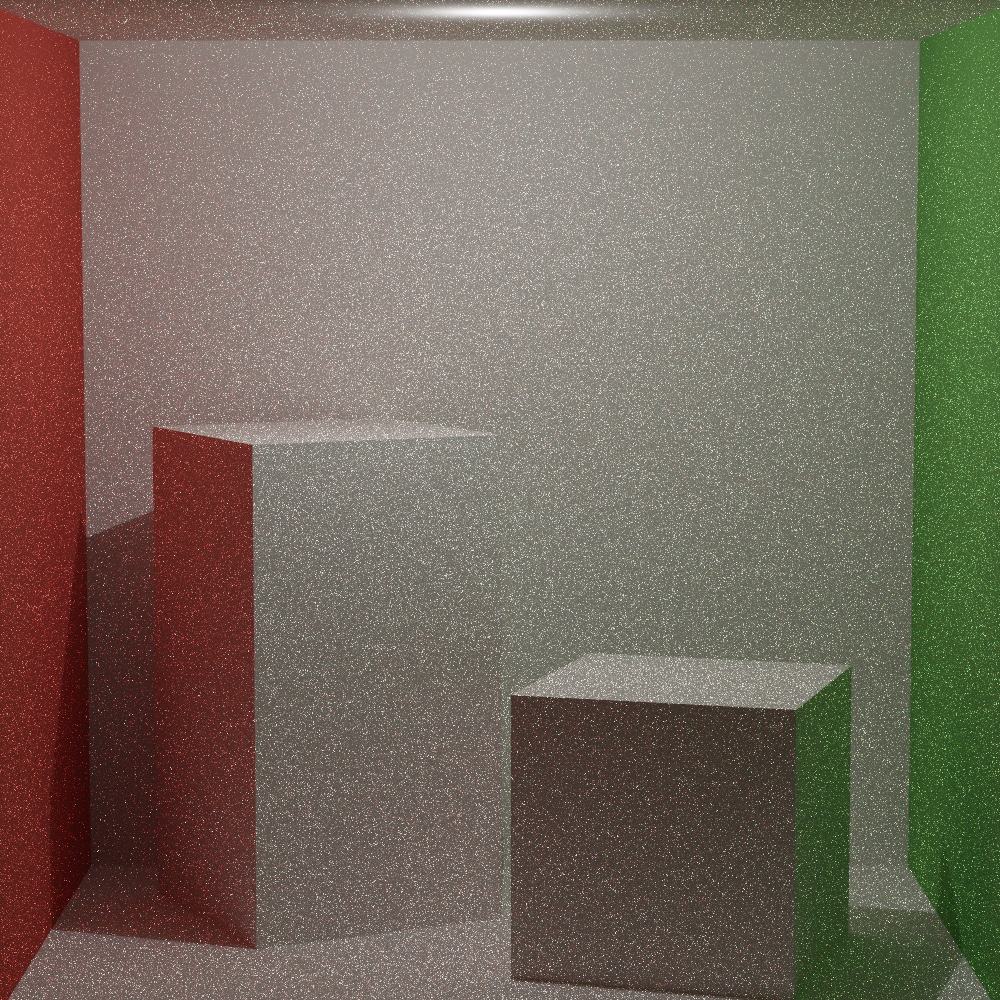
Point and spot lights only use the light strategy. A BSDF-sampled ray has zero probability of hitting a point, so the second estimator would only add noise.
Russian Roulette
After the third bounce, the path survives with probability q = max(throughput.rgb), floored at 0.05, and surviving paths are divided by q to stay unbiased. I implemented it but honestly I’m not sure I can feel any noticeable difference.
Light Sampling
Each light type has its own sampler and pdf:
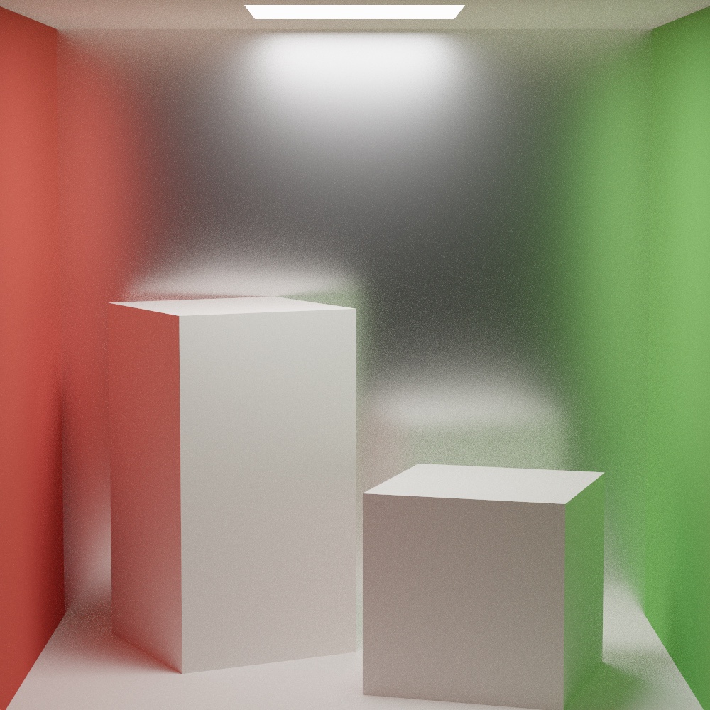
- Rectangle area light. A uniform point on the unit quad, transformed into world space. The area pdf
1/areais converted to solid angle by multiplying byr²and dividing by the cosine at the light. Back-facing samples return zero. - Sphere area light. Uniform sampling of the cone of directions that subtend the sphere, with
cosThetaMaxfrom the distance to the center and the radius, so no samples are wasted on the far side. - Point light. Inverse-square falloff, pdf is just
1/numLights. - Spot light. Same as point, with intensity from a
smoothstepbetween the outer and inner cone angles. - Environment light. Cosine-weighted hemisphere sample around the normal. The shadow ray has to escape the scene entirely for the sample to count, and the map is looked up by converting the direction to equirectangular UVs.
Materials
Diffuse and Oren-Nayar
Lambert is albedo / pi. Oren-Nayar adds the roughness term from the two angles and the azimuth difference, using the standard A and B coefficients from sigma.
512spp, 1000x1000, denoised. ACES tone-mapping. Oren-Nayar model using sigma = 0.8.
| Lambertian | Oren-Nayar (Energy Conserve Fix) | Oren-Nayar |
|---|---|---|
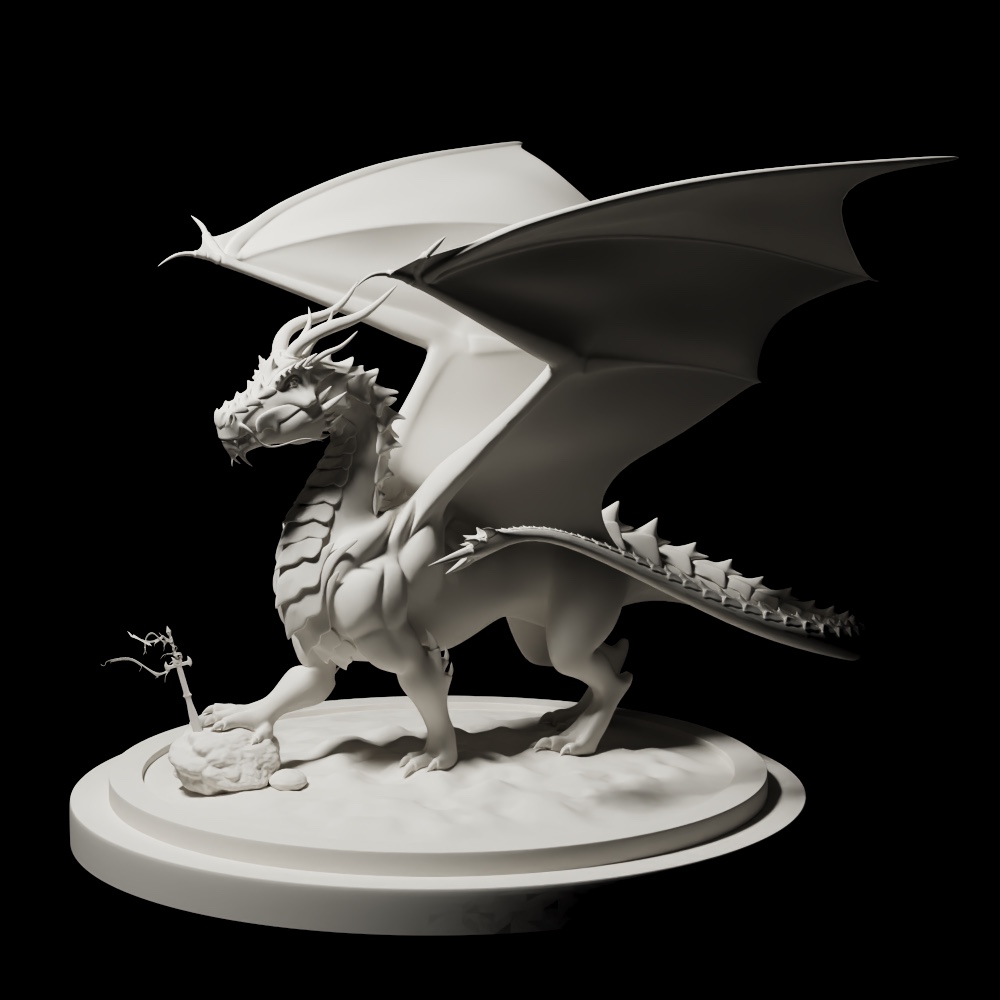 | 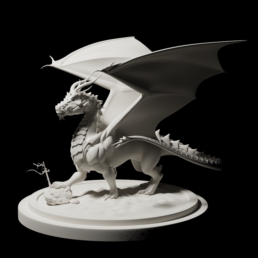 | 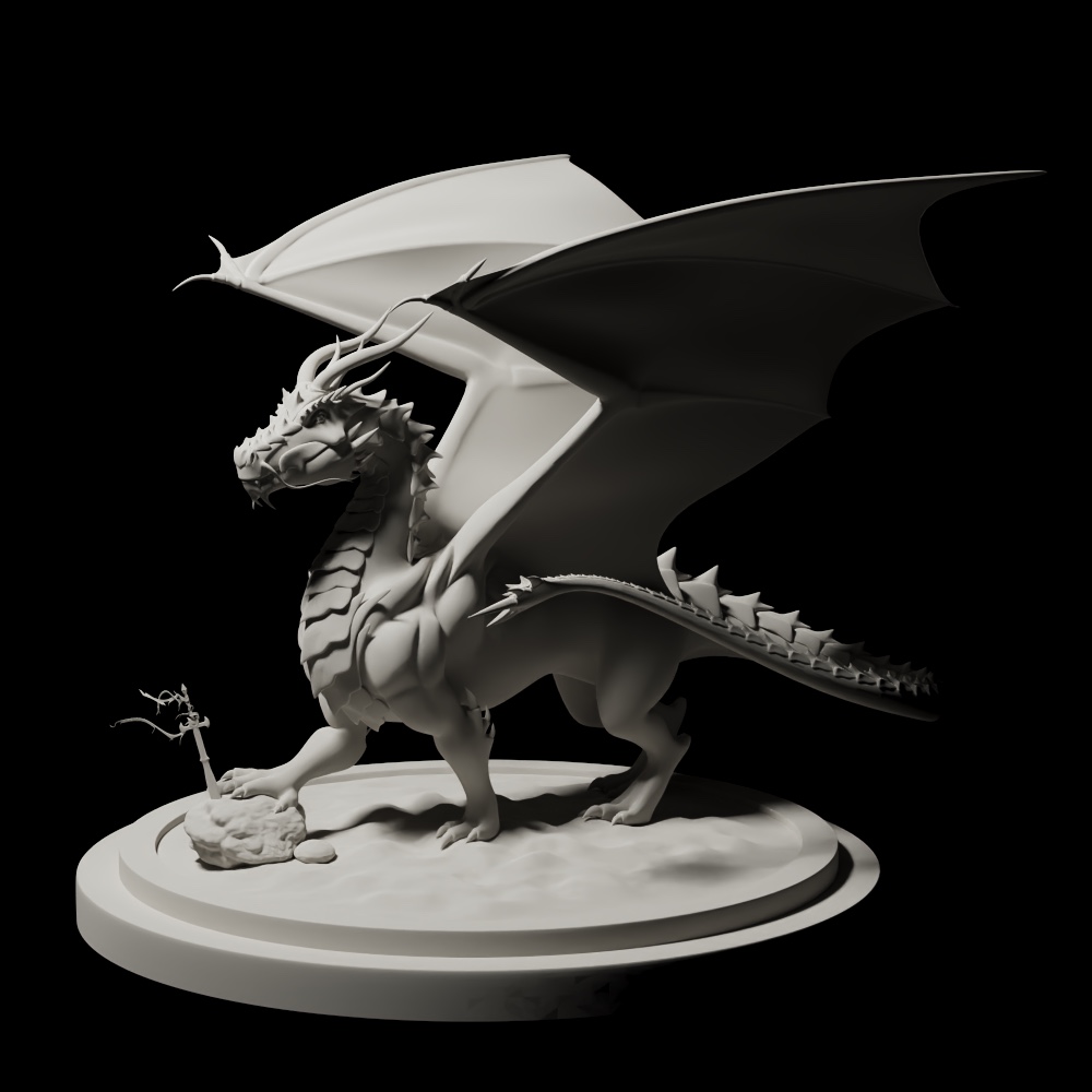 |
One can see that the regular simplified Oren-Nayar is visibly darker than the Lambertian one. This is because the most common simplified Oren-Nayar model is actually not energy conserving: it loses light energy because A < 1 for any sigma > 0. The middle render is after applying a small energy compensation factor, 1 / (1 - 0.33 sigma² / (sigma² + 0.09)), which scales the lobe back up to what Lambert would reflect.
Personally I think the more noticeable parts of the render differences are the stone and the dragon’s chin, where Oren-Nayar preserves the light energy a lot better at those grazing angles. Although I feel like it is so minor I’m slightly worried if I messed up somewhere.
Models from Benedikt Bitterli’s rendering resources
Specular Reflection, Transmission, and Glass
Perfect mirrors and perfect transmission are delta BSDFs, so Sample_f returns the one valid direction with pdf 1 and f() returns zero for any other direction. Glass evaluates the dielectric Fresnel term for the incoming angle (with the indices swapped when the ray is inside the medium, and total internal reflection returning full reflectance), then picks reflection or refraction with probability equal to that Fresnel value. Choosing stochastically instead of tracing both branches keeps one path per pixel per frame.
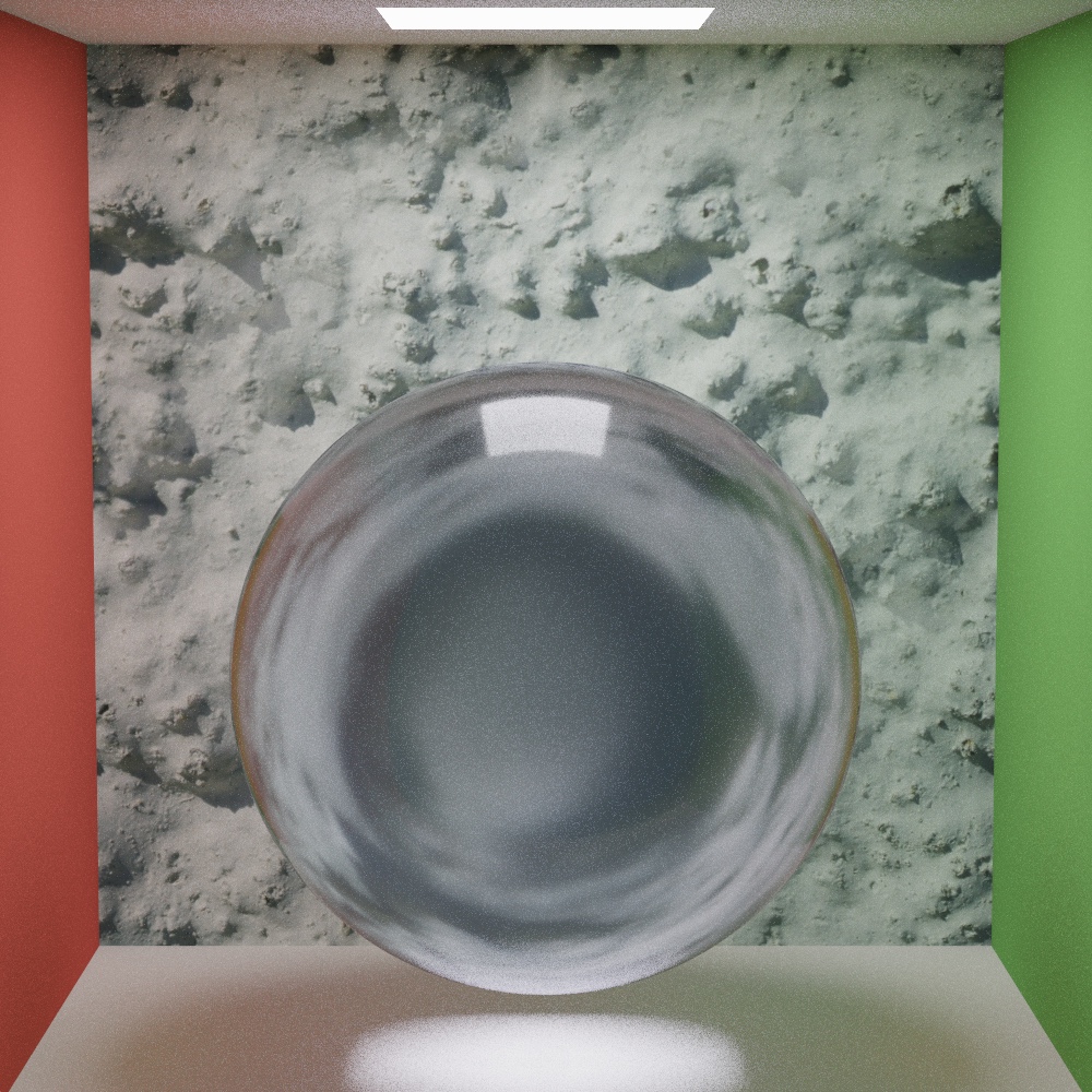
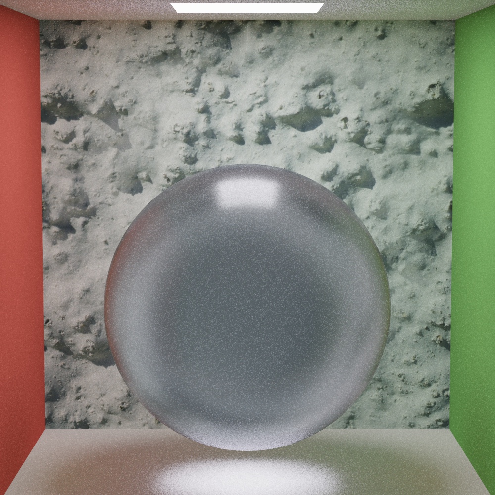
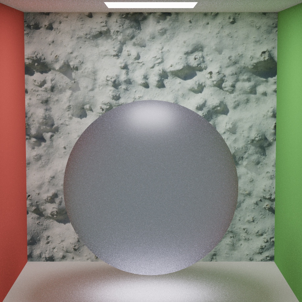
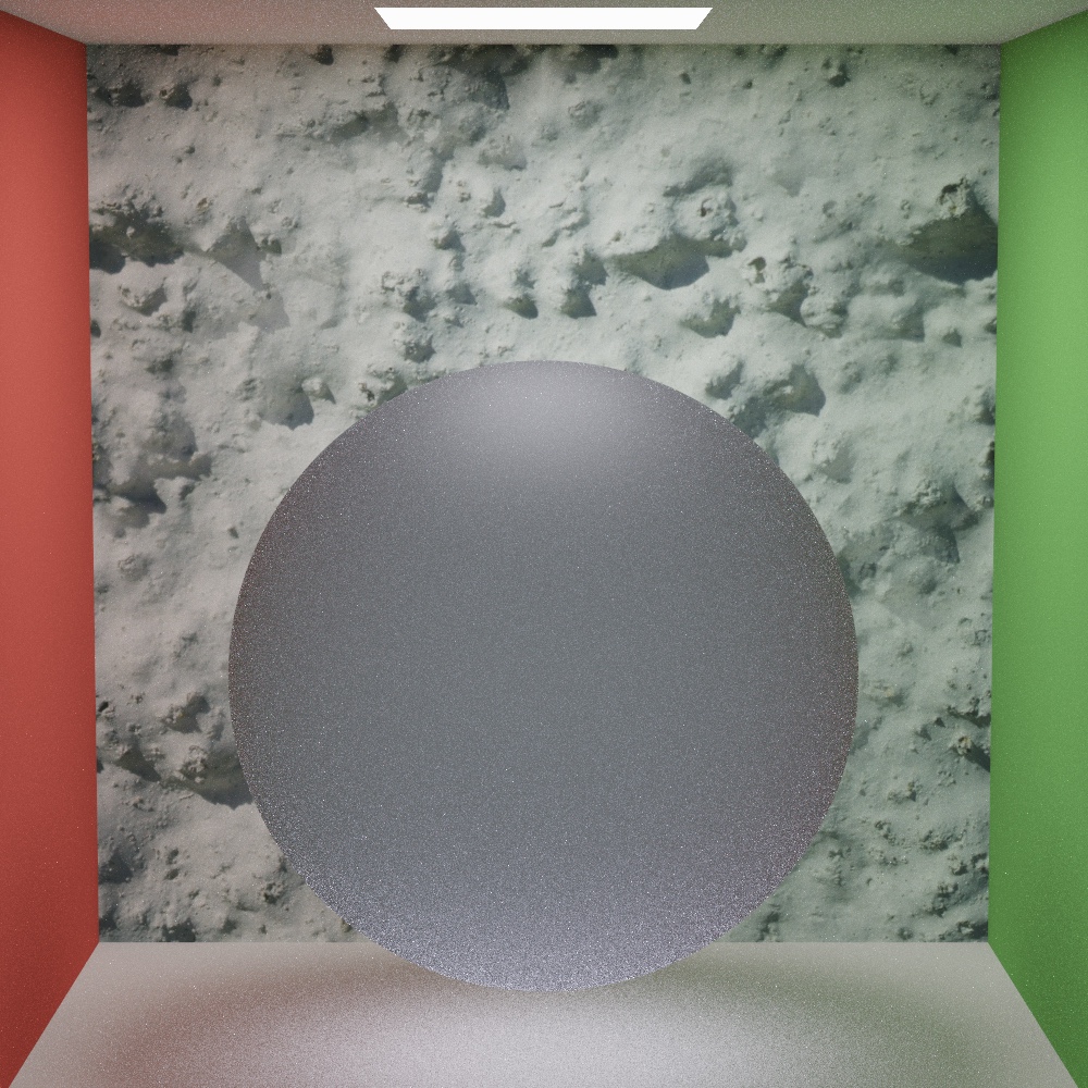
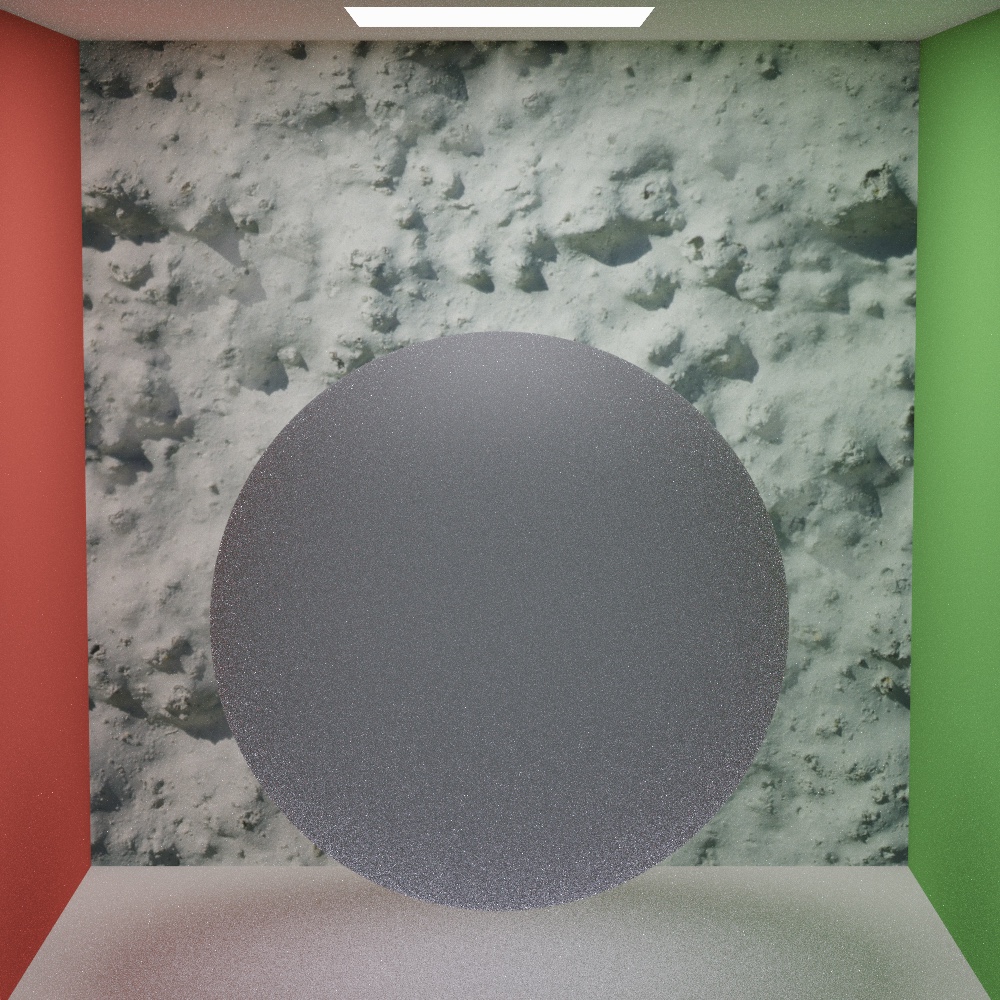
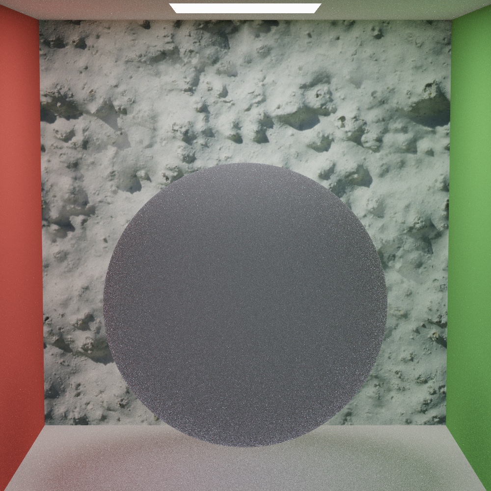
Trowbridge-Reitz Microfacet Specular Reflection & Transmission
Reflection samples a microfacet normal wh from the Trowbridge-Reitz distribution and reflects wo about it. Transmission refracts wo through the sampled wh instead, and the half vector for evaluation becomes normalize(wo + eta * wi) with eta flipped depending on which side of the surface wo is on. The pdf picks up the transmission Jacobian |wi·wh| eta² / (wo·wh + eta wi·wh)², and the BTDF gets the matching denominator plus a (1 - F) factor.
Microfacet glass combines the two. It samples wh first, evaluates Fresnel against that microfacet normal rather than the macro normal, and then chooses reflection with probability F or refraction with probability 1 - F, scaling each pdf by the same probability so f / pdf stays correct. If refraction through the sampled microfacet hits total internal reflection, the sample falls back to reflection.
1024spp, 1000x1000, no denoising. Reinhard tone-mapping
| roughness 0.01 | roughness 0.05 | roughness 0.25 |
|---|---|---|
 |  |  |
| roughness 0.50 | roughness 0.75 | roughness 0.95 |
|---|---|---|
 |  |  |
Conductive Material Fresnel Reflectance
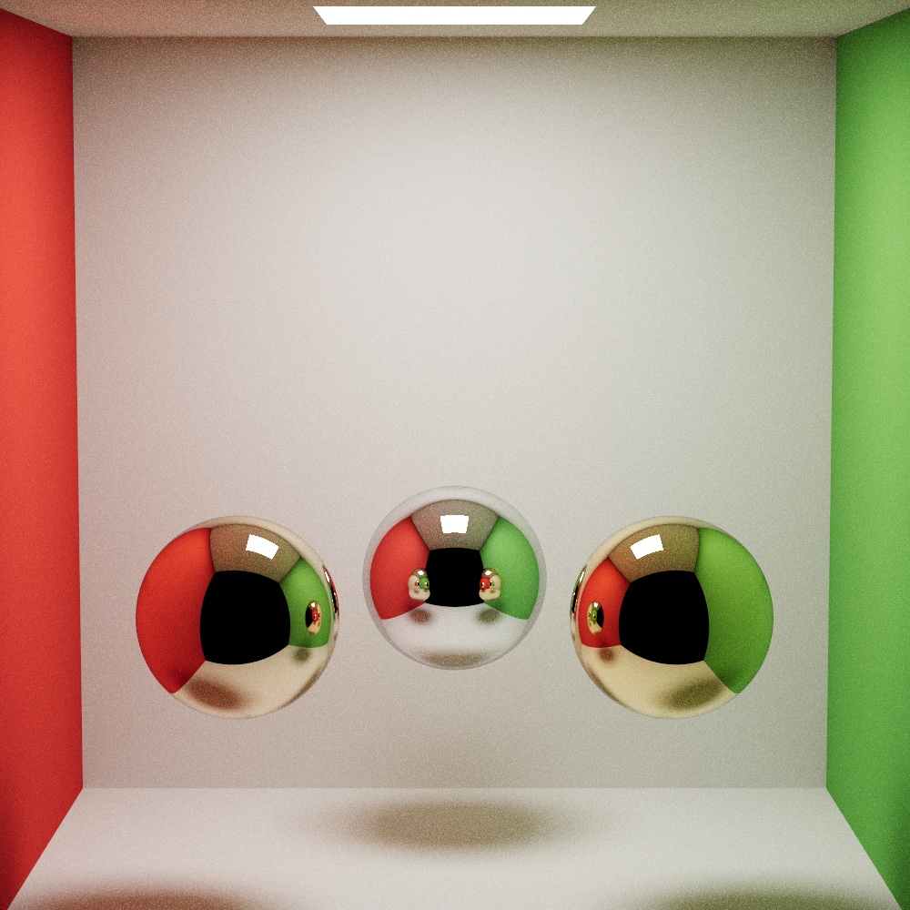
Conductors use the full complex-IOR Fresnel equations with eta and k per RGB channel, evaluated for perfect mirror reflection. The three metals below are the tabulated values for gold, copper, and aluminum.
Gold: eta [0.183, 0.421, 1.373], k [3.424, 2.346, 1.770]
Copper: eta [0.271, 0.677, 1.316], k [3.609, 2.625, 2.292]
Aluminum: eta [1.655, 0.879, 0.520], k [9.224, 6.270, 4.837]
Textures
Materials can reference an albedo map (sampled and converted from sRGB to linear), a normal map applied in the tangent frame of the geometric normal, and a roughness map that overrides the material’s scalar roughness. All three are indices into a sampler array, so a mesh can use any combination.
Meshes and BVH
Triangle meshes get a BVH built on the CPU with the surface area heuristic:
- Compute the bounds of the current range of triangles and the bounds of their centroids.
- Split the centroid bounds along the longest axis into 12 buckets, and drop each triangle into a bucket by its centroid.
- For each of the 11 possible splits, cost = 0.125 (traversal) + (count_left * area_left + count_right * area_right) / area_parent.
- Take the cheapest split. If it degenerates (everything on one side), fall back to splitting the range in half.
Leaves hold a single triangle. The tree is then flattened into two vec4 per node: bounding box min plus a secondary index, and bounding box max plus a triangle count. The left child is always the next node in the array, so only the right child’s index needs to be stored. The flat array goes to the GPU as an SSBO, and the triangles themselves live in a texture, fetched by index.
Traversal in the shader is an explicit stack of 64 node indices. For each node it runs the slab test, skips boxes that are missed or entirely behind the ray, and also skips boxes whose entry distance is already past the closest hit found so far. Leaves run Möller-Trumbore and interpolate normals and UVs with barycentric weights.
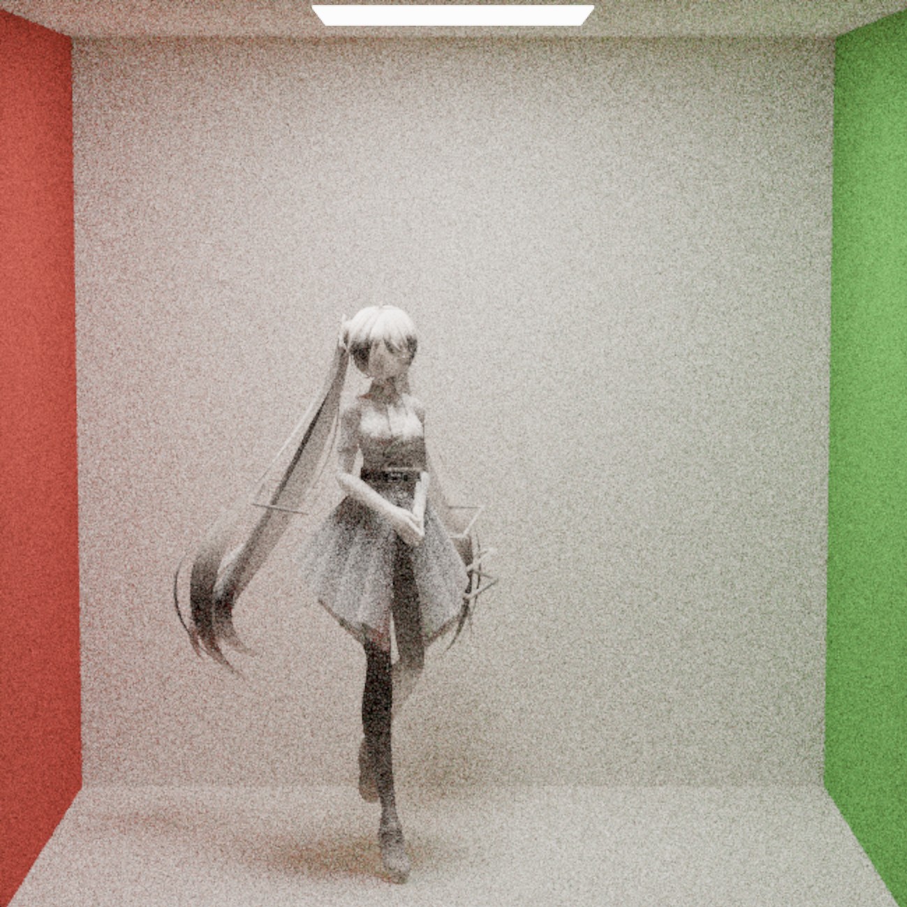
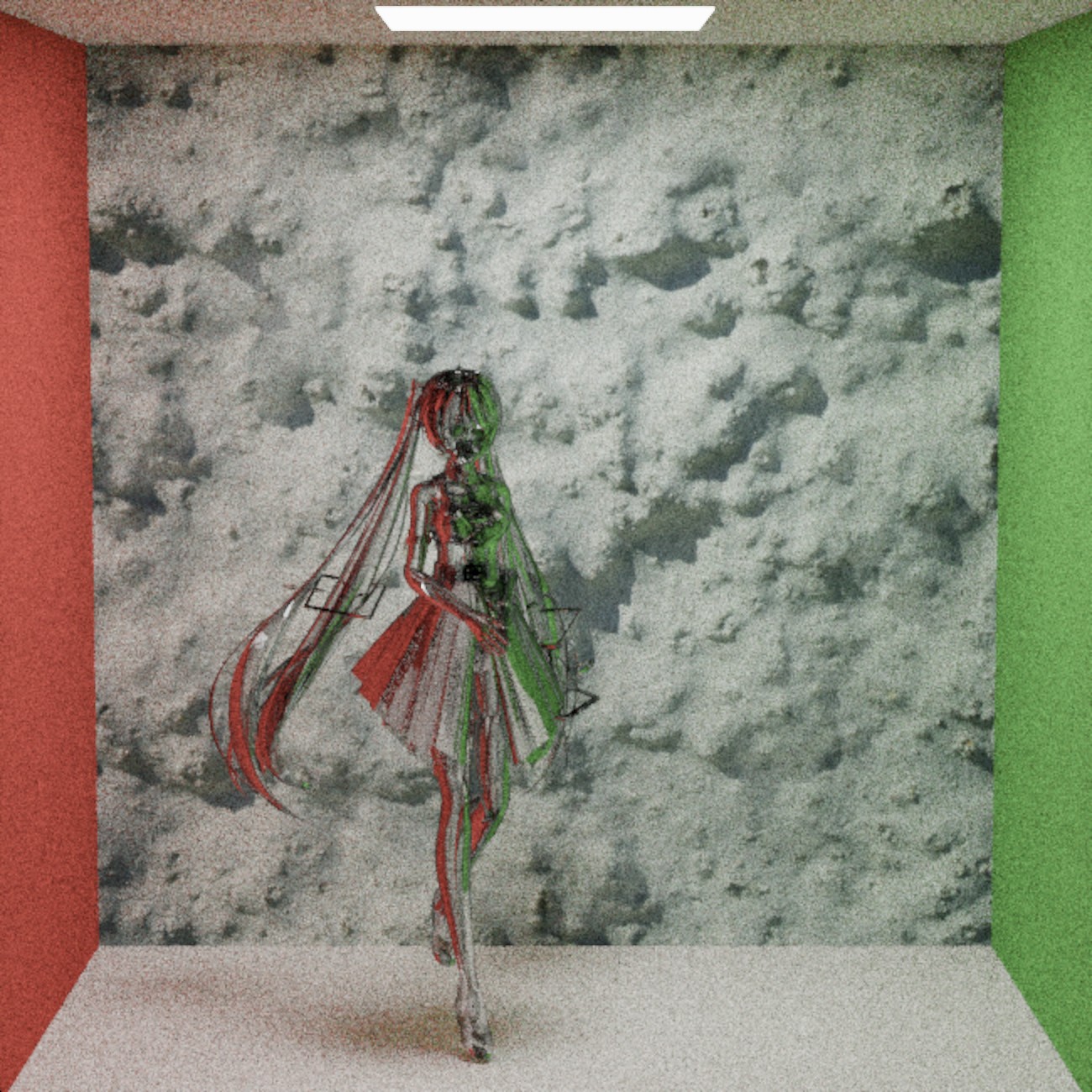
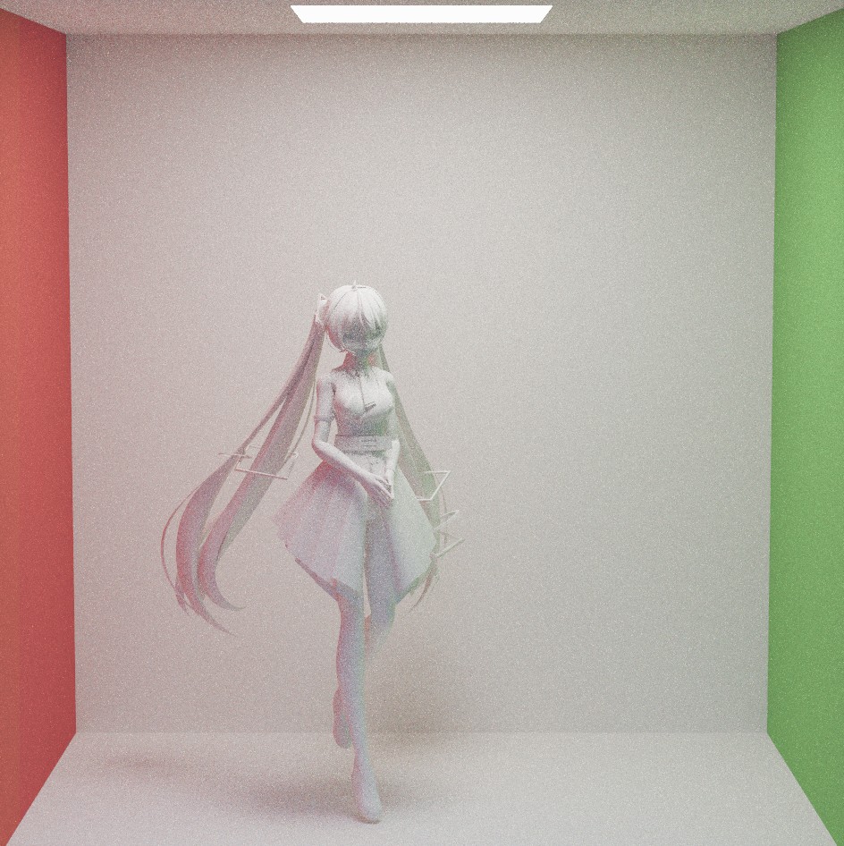
One noticeable bug I ran into: the interpolated mesh normal was coming back in object space, so any mesh with a rotation or scale on it shaded wrong. It resulted in some rather interesting gradient colors so I thought I’d put it here. The fix was just properly applying the inverse transpose of the mesh transform to it.
| Matte, broken normals | Glass, broken normals | Fixed |
|---|---|---|
 |  |  |
Depth of Field
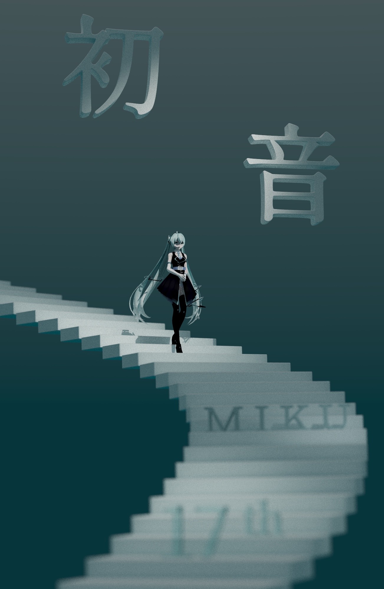
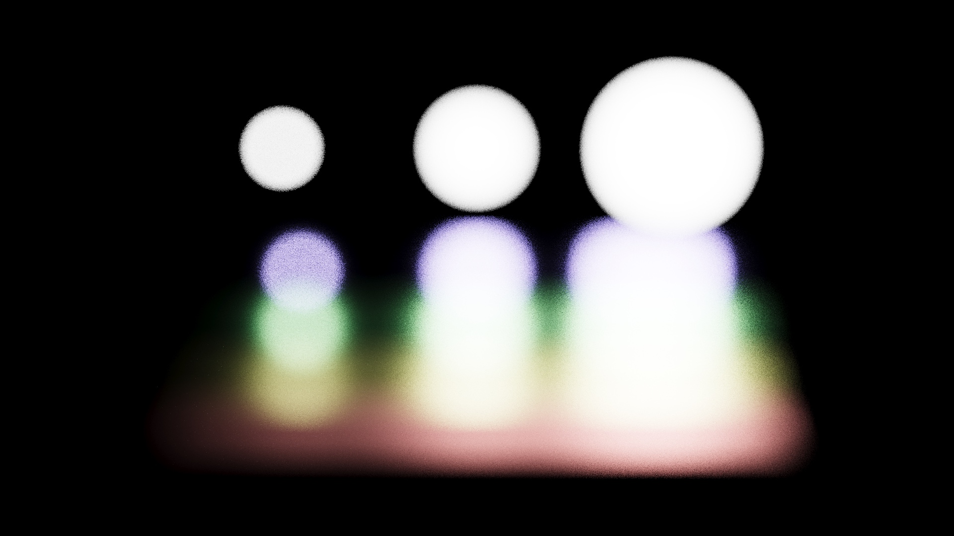
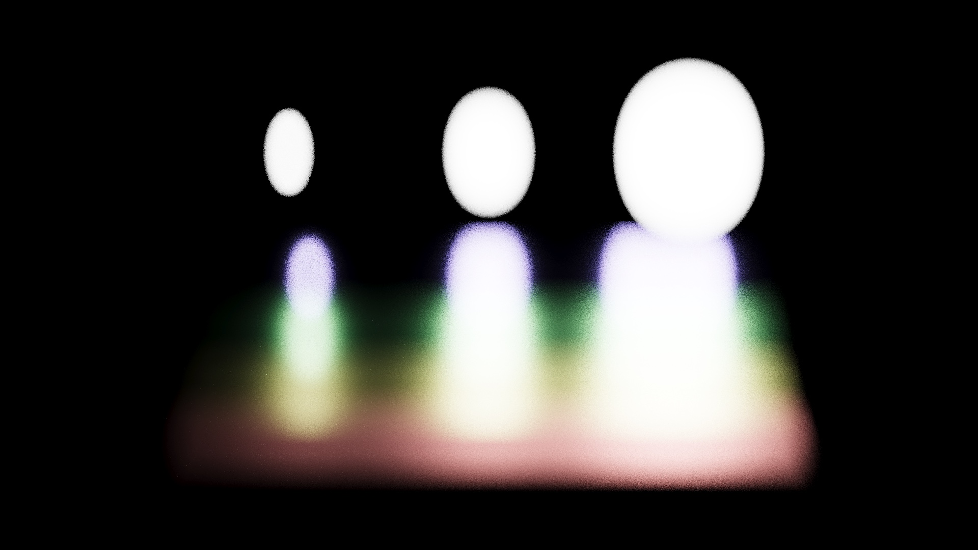
The camera is a thin lens. For each pixel the pinhole ray is extended to the focal plane (t = focalDist / (dir · forward)), then the ray origin is moved to a random point on the lens disk via concentric disk sampling, and the new direction points from that lens point to the focal point. Anamorphic bokeh is one extra line: the lens sample’s x coordinate is divided by a squeeze factor before it’s scaled by the aperture, which turns the circle of confusion into a tall oval.
128spp, 1303x2000, no denoising. ACES tone-mapping
| No DOF | DOF |
|---|---|
|  |
| Spherical | Anamorphic |
|---|---|
 |  |
Environment Map and Procedural Sky
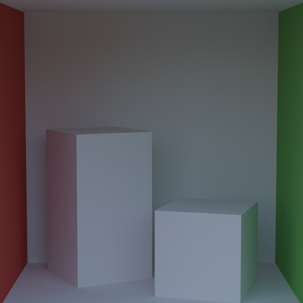
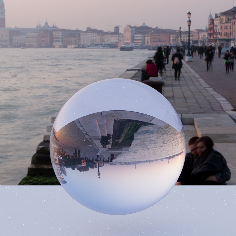
Escaped rays and the environment light both look up the same function. With an HDR map loaded, the direction is converted to equirectangular UVs with atan and asin. The cover render uses a procedural sky instead: a gradient from a dark teal at the horizon to white at the zenith, scaled down so it reads as fill light rather than a light source.
1024spp, 1000x1000, 2s. Reinhard tone-mapping
| Cornell Box | Glass Sphere |
|---|---|
 |  |
See the cover render at top for the procedural skybox.
Intel OpenImageDenoise
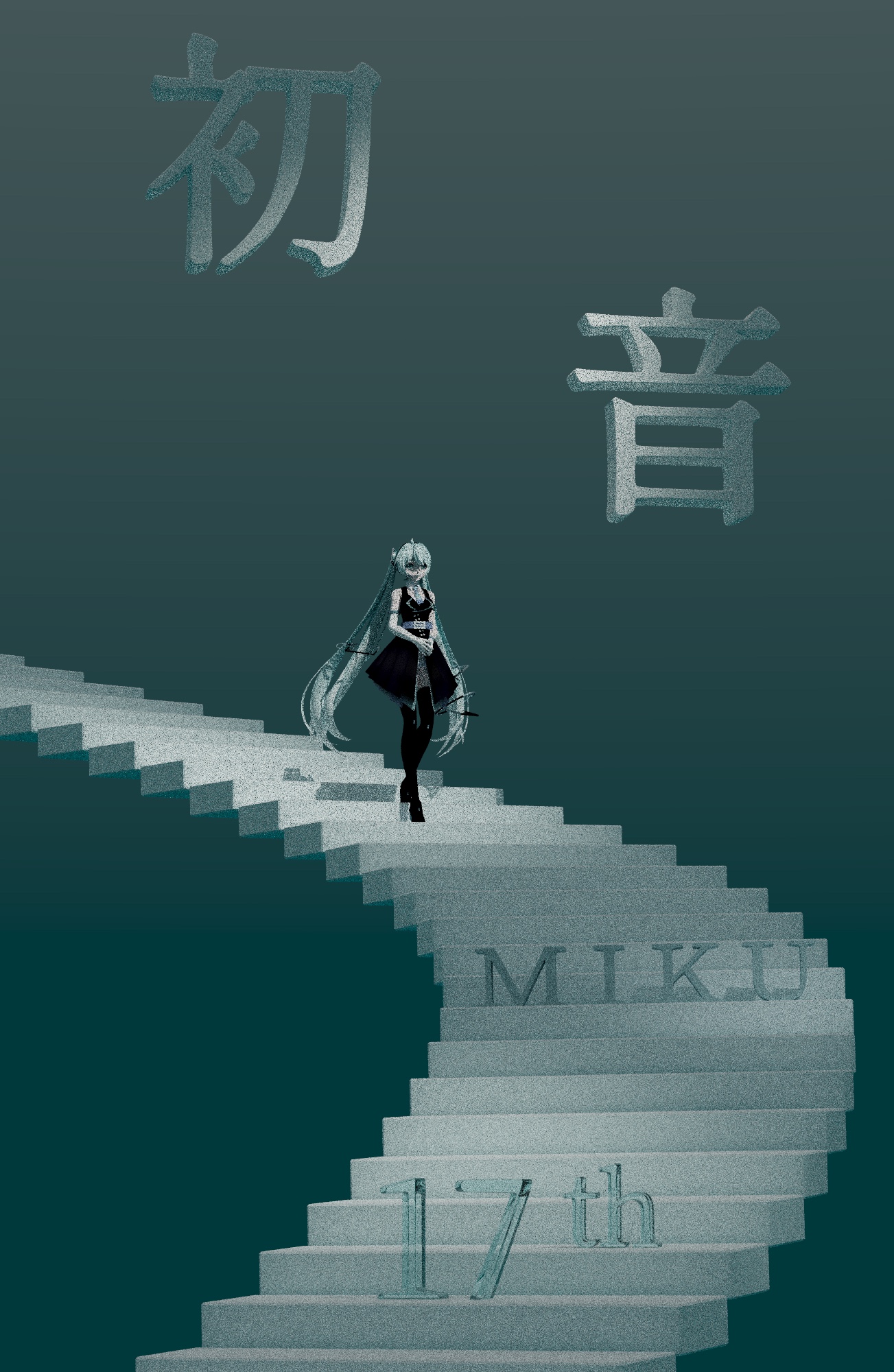
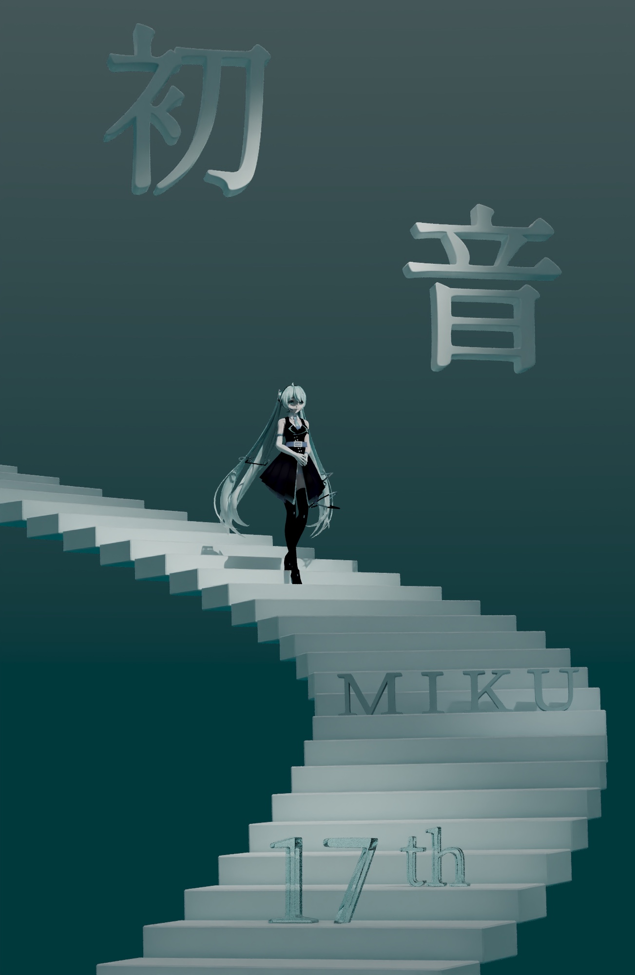
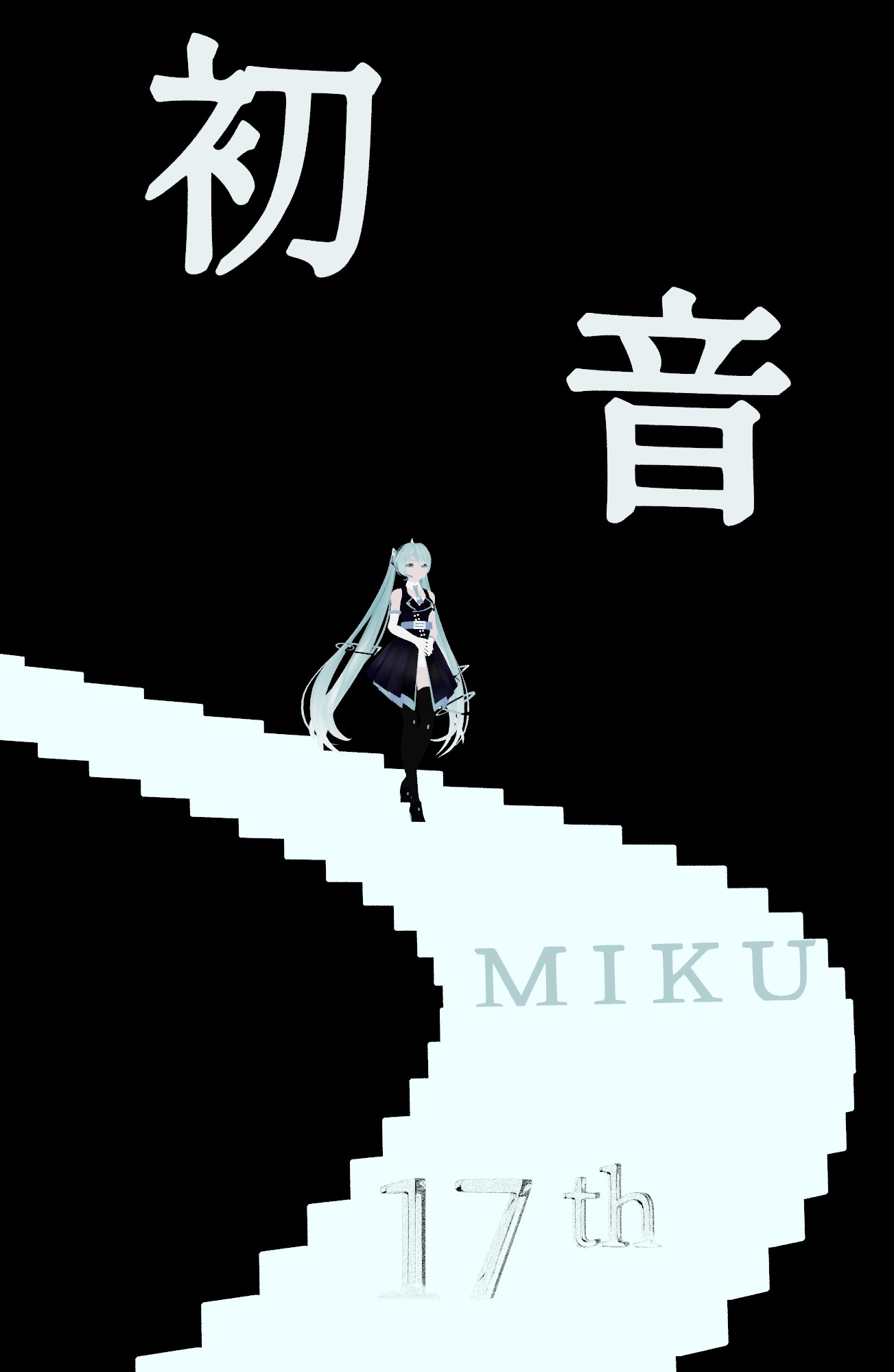
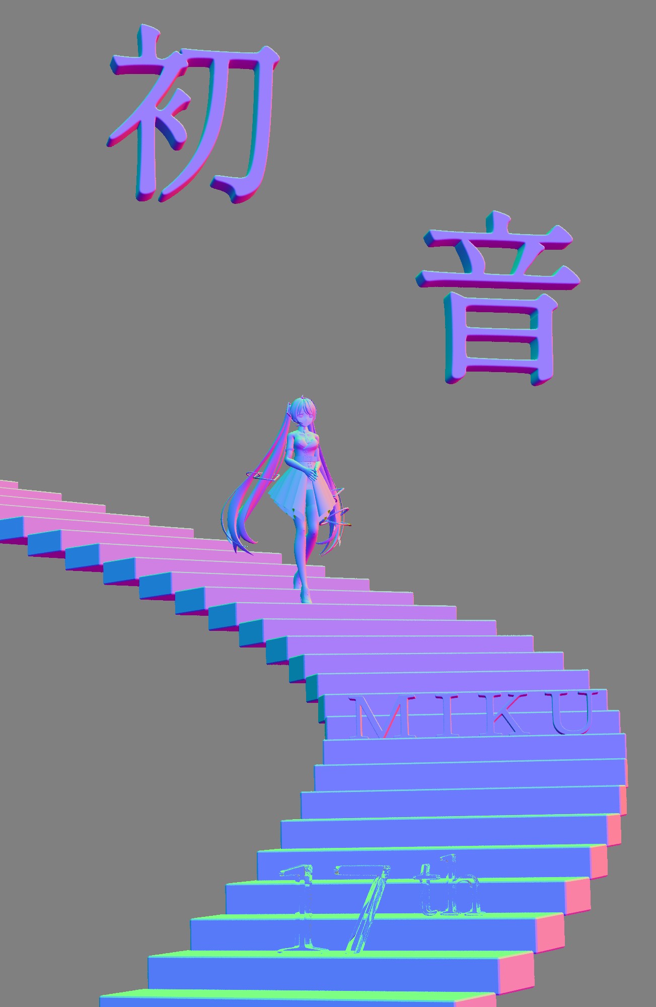
The path tracer writes three render targets per frame: color, albedo, and normal. The albedo and normal are captured at the first non-specular hit rather than the first hit, so through a glass sphere the AOVs describe what’s behind the glass instead of the glass surface. All three accumulate the same way as color. OIDN’s RT filter runs in HDR mode with the albedo and normal buffers as guides.
12spp, 1303x2000. Raw and denoised: ACES tone-mapping. Albedo: linear reflectance, gamma only. Normal: world-space, remapped from [-1, 1] to [0, 1], no tone curve. Both guides are captured at the first non-specular hit, so the glass “17th” text shows the stairs behind it, and black where its reflection reaches the sky.
| Raw | Denoised |
|---|---|
 |  |
| Albedo | Normal |
|---|---|
 |  |
Offline CLI Render
I got really sick of Qt crashing on Linux and file dialogs not working, hence this. Passing --scene skips the UI entirely: the renderer runs a fixed number of samples into an offscreen framebuffer at the requested resolution, optionally denoises, writes the files, prints the render time, and exits.
./ShaderPathtracer --scene <file.json>   headless render (required for CLI mode)
  --samples <n>        samples per pixel (default 256)
  --width / --height   resolution (default 800x600)
  --output <dir>       output directory under path_tracer/render/
  --oidn               denoise the final image
  --aovs               also write the albedo and normal passes
  --png / --hdr        output format (PNG if neither is given)
  --envmap <file.hdr>  environment map
  --reinhard           Reinhard tone mapping instead of ACES
  --sky                procedural skybox (--envmap takes precedence)
Since the tracer needs a real OpenGL context, offscreen doesn’t work. When no DISPLAY is set the launcher looks for a running Wayland socket and attaches to it, which is what lets it render over SSH.
NEE Demo Renders
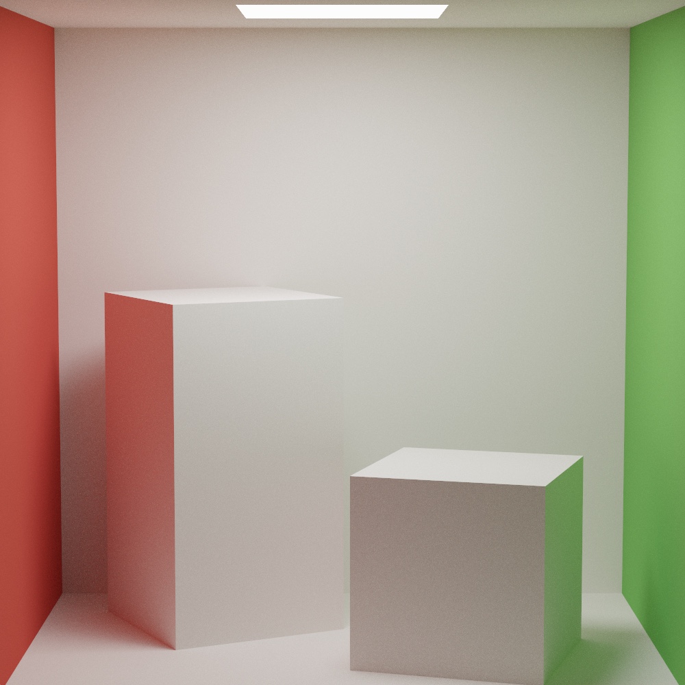
1024spp, 1000x1000
| Area Light | Spot Light | Sphere Light |
|---|---|---|
 |  |  |
| Point Light | Rough Mirror | Veach Scene |
|---|---|---|
 |  | 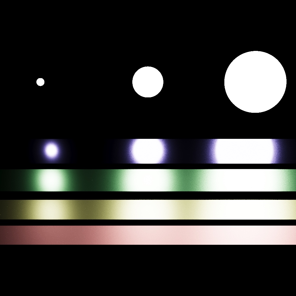 |
Tools Used
C++, GLSL, OpenGL, Qt, Intel OpenImageDenoise